
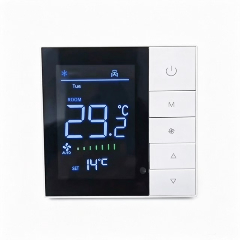
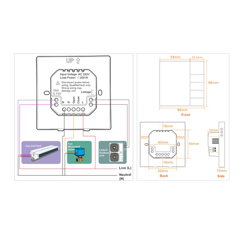
8812F DC Brushless Thermostat for FCU
Key Specifications
Below you will find the full key specifications of the 8812F DC Brushless Thermostat for FCU:
· Micro-computer control · LCD screen with physical buttons
· 2-pipe / 4-pipe compatible · AC 100-240V, 50/60Hz
· 0-10V DC fan control output · Cooling / Heating / Ventilation
· 86x86x10mm
Our 8812F DC brushless thermostat is designed for 2-pipe or 4-pipe fan coil units and dual supply water systems. It uses a built-in temperature sensor to accurately sense indoor temperature and automatically adjusts the fan coil unit and motorized valve status according to user-defined parameters. When used in building automation environments, HVAC devices often rely on industry communication standards. For more information about the Modbus protocol, visit the Wikipedia page.
Why Choose 8812F DC Brushless Thermostat for FCU
Control your fan coil unit and motorized valve with reliable physical button operation and automatic temperature sensing.
· Smart Micro-computer Control – Automatically senses indoor temperature and adjusts fan/valve outputs to save energy.
· Standard 86-Type Size – Compact 86x86x10mm design, easy retrofit installation for building renovation projects.
· Physical Button & LCD Display – Simple, stable, and reliable interface without touch controls.
8812F DC Brushless Thermostat Operation Functions
All setting operations of the 8812F DC Brushless Thermostat are listed below.
1. Power On/Off
– Enter: While off, press the Power button to turn on. While on, press the Power button to turn off.
2. Mode Selection
– Enter: While on, press the Mode button.
– Adjust: The display shows the cooling, heating, or ventilation mode icon.
3. Fan Speed Selection
– Enter: While on, press the Fan Speed button.
– Adjust: Press Fan Speed to select low, medium, high, or auto fan speed. In auto fan speed, the thermostat automatically adjusts based on the temperature difference.
4. Temperature Setting
– Adjust: Press the Up or Down buttons to set the target temperature.
– Range: 5°C to 35°C.
5. Child Lock Function
– Toggle: While on, press and hold both Up and Down buttons for 5 seconds to enable/disable. When enabled, all buttons except Power are locked.
6. Clock Setting
– Enter: While on, press and hold the Mode button for 5 seconds to enter the clock adjustment interface.
– Adjust: Press the Up or Down buttons to change values, then press Mode to switch to the next step.
– Save & Exit: Press the Power button.
7. Sleep Mode
– Enter: While on, press and hold the Mode button for 3 seconds. The sleep icon flashes.
– Adjust: Press the Mode button to confirm. Press Mode again to cancel.
8.Timer Function
– Enter: While on, press and hold the Mode button for 3 seconds. The sleep icon flashes. Press Mode again to switch to the timer setting interface.
– Adjust: Press Mode to cycle through P1 minute timer, P1 hour timer, P1 off timer, and P1 on/off confirmation. Use Up/Down buttons to change values.
9. Factory Reset
– Action: While on, press and hold the Up and Mode buttons together for 5 seconds. The full screen displays for 2 seconds and then shuts down, indicating factory reset is successful.
10. Sensor Fault Alarm
– Trigger: When the sensor fails.
– Display: Shows “E1” on the screen and turns off all outputs. Returns to normal after the fault is cleared.
11. Low-Temperature Protection
– Condition: Activated when the low-temperature protection function is enabled and the indoor temperature drops below the protection temperature.
– Action: The valve and fan outputs are automatically turned on. When the indoor temperature rises above the protection temperature, the outputs are turned off. This cycle repeats.