RS485 Modbus Thermostat Setup: step-by-step Guide
In this article, you will learn:
· What You Need Before Starting
· Step 1: Wiring the RS485 Bus
· Step 2: Configuring Baud Rate and Parity
· Step 3: Testing the Communication
· Common Troubleshooting Tips
Click any topic above to jump directly to that section.
If you are working with Modbus thermostats in an HVAC system, setting up a reliable RS485 Modbus thermostat setup is one of the most important steps. RS485 is the physical layer that allows multiple Modbus devices — thermostats, sensors, controllers — to communicate with each other over long distances.
According to GB/T 19582.1-2008 Industrial automation network specification based on Modbus protocol – Part 1: Modbus application protocol, MODBUS is an application-layer messaging protocol that provides client/server communication between devices connected on different types of buses or networks. At the physical layer, MODBUS serial links commonly use EIA/TIA-485 (RS485) or EIA/TIA-232 (RS232) interfaces. Among these, RS485 is the most widely used for building automation and HVAC applications due to its support for long-distance communication and multi-device networking.
A proper RS485 setup ensures stable data transmission, reduces errors, and makes troubleshooting much easier. In this guide, we will walk through the basic steps for setting up RS485 communication for Modbus thermostats in typical HVAC installations.
What You Need Before Starting?
Before you begin your RS485 Modbus thermostat setup, make sure you have the following components ready:
· Modbus thermostat(s) with built‑in RS485 interface
· RS485 to USB or RS485 to serial converter (for connecting to a PC)
· Twisted‑pair shielded cable (recommended: 24 AWG or lower)
· 120Ω termination resistors (if required by your network)
· A PC with Modbus debugging software (such as ModScan, QModMaster, or similar)
· Documentation for your thermostat (baud rate, parity, and address settings)
Having these items prepared before you start will save time and reduce the chance of errors during setup.
Step 1: Wiring the RS485 Bus
RS485 uses a daisy‑chain topology, meaning each device is connected in sequence along the same two wires (A and B). Avoid star or tree wiring, as these can cause signal reflection and communication failures.
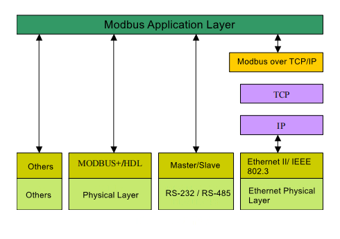
Figure: MODBUS communication stack showing physical layer support for EIA/TIA-232 and EIA/TIA-485 interfaces. (Source: GB/T 19582.1-2008)
Basic Wiring Rules:
· Connect all A terminals together.
· Connect all B terminals together.
· Use a shielded twisted‑pair cable for the bus.
· Connect the shield to ground at one end only (to avoid ground loops).
· Keep the total cable length under 1200 meters for reliable communication (theoretical maximum at lower baud rates; actual distance may vary depending on cable quality, environment, and number of devices).
· Place a 120Ω termination resistor at each end of the bus.
Example Connection Order:
PC (RS485 converter) → Thermostat 1 → Thermostat 2 → Thermostat 3 → (Termination resistor at the end)
[Insert your MODBUS communication stack diagram here]
Figure: MODBUS communication stack showing physical layer support for EIA/TIA-232 and EIA/TIA-485 interfaces. (Source: GB/T 19582.1-2008)
If your network has more than 32 devices, you may need a repeater to extend the bus or maintain signal quality. For most HVAC installations, however, the number of devices is typically well below this limit.
Step 2: Configuring Baud Rate and Parity
If any RS485 Modbus thermostat setup must use the same communication settings. The most common configuration for Modbus RTU is:
· Baud rate: 9600 bps (most common)
· Data bits: 8
· Stop bits: 1
· Parity: None (or Even, depending on device)
How to Check and Set:
- Access the configuration menu on each thermostat (refer to the product manual).
- Set the baud rate, parity, and stop bits to match the master device.
- Assign a unique Modbus address to each thermostat (e.g., 1, 2, 3…).
If you are unsure about the settings, start with 9600 bps, 8 data bits, 1 stop bit, and no parity — this works for most installations and can be adjusted later if needed.
Step 3: Testing the Communication
Once wiring and configuration are complete, it is time to test the network.
Using Modbus Debugging Software:
- Connect the RS485 converter to your PC.
- Open your Modbus debugging tool.
- Set the software to use the same baud rate and parity as your thermostats.
- Enter the Modbus address of a thermostat.
- Try to read a register (e.g., current temperature or setpoint).
If the software returns a value without errors, the communication is working correctly. If you receive a timeout or error response, check the wiring, address, and settings again.
For additional context on Modbus integration, you may also refer to our Modbus integration guide.
Common Troubleshooting Tips
Even with careful setup, issues can occur. Here are some of the most common problems and how to fix them:
Issue Likely Cause Solution
No response from device Incorrect wiring or missing termination resistor Check A/B connections, add termination resistors at both ends
Intermittent communication Poor cable quality or electrical noise Use shielded twisted‑pair cable, check grounding
Device responds with error Baud rate or parity mismatch Verify settings match across all devices
Duplicate address conflict Two devices share the same Modbus address Assign unique addresses to each device
If you still cannot establish communication after checking these points, try reducing the baud rate to 2400 or 4800 bps — this can improve stability over longer cables or in electrically noisy environments.
After wiring and communication verification, refer to the practical Modbus thermostat examples to read real‑time temperature and write target setpoints to your device.
Related Reading:
· What is Modbus RTU and How Does It Work in HVAC Systems?
· Modbus Thermostat in Fan Coil Unit Systems: A Typical Application.
· AI Vision RFID Library Management System with Modbus Integration .
For more guidance on RS485 Modbus thermostat setup, browse our relative guides or contact our team for a free consultation.