Common Wiring & Application Pitfalls for Water-System Fan-Coil Thermostats
In this article, you will learn:
- Common Wiring Mistakes on Water-System FCU Thermostats
- Application Pitfalls in Retrofit Projects
- Why Relay Endurance Testing Matters
- Pre-Commissioning Checklist
Click any topic above to jump directly to that section.
Mastering water-system fan coil thermostat wiring is essential to avoid common application pitfalls. In water-system fan-coil unit (FCU) retrofit projects, the thermostat is often the last component to be installed and the first to be blamed when something does not work. More often than not, the problem is not the thermostat itself — it is the wiring or the application logic behind it.
This guide covers the most common fan coil thermostat wiring and application pitfalls that installers encounter when replacing or upgrading water-system fan coil thermostats in office buildings, hotels, and commercial facilities.
Common Fan Coil Thermostat Wiring Mistakes on Water-System FCU Thermostats
1. Reversing the Live and Neutral Wires
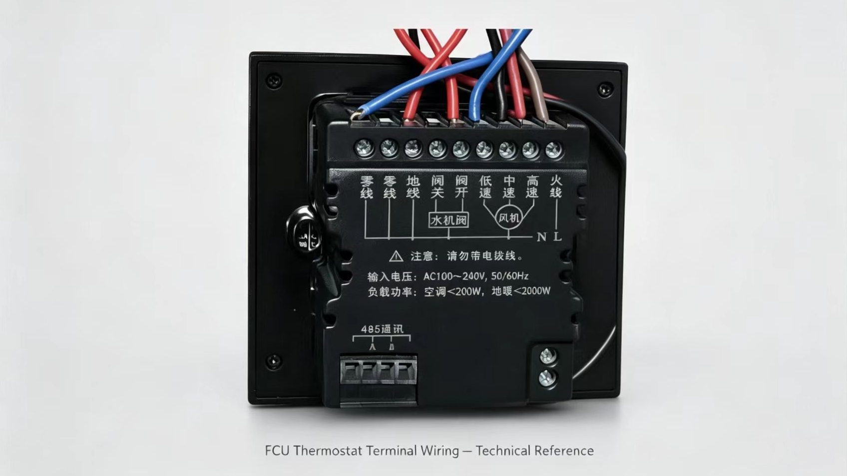
On most FCU thermostats, the power supply terminals are labeled L (Live) and N (Neutral). Reversing these two wires is a common mistake, especially in older buildings where wiring colors are inconsistent.
Consequence: The thermostat may power on but behave erratically, or it may be permanently damaged.
Prevention: Always verify the live wire with a voltage tester before connecting. Never assume red is live and black is neutral — in older buildings, this is not always the case.
2. Incorrect Valve Wiring (Open/Close Terminals)
Water-system FCU thermostats typically control motorized on/off valves through two output terminals: Valve Open and Valve Close. Swapping these two wires will cause the valve to operate in reverse — the thermostat calls for heating, but the valve closes instead of opening.
Consequence: The room does not reach the setpoint, and the thermostat may appear to be faulty when it is actually working correctly.
Prevention: Before connecting, check the valve actuator wiring diagram. Most actuators have three wires: Live, Neutral, and a control signal. Confirm which terminal receives power for “open” and which receives power for “close.”
3. Fan Speed Wiring (L / M / H Terminals)
FCU thermostats control the fan motor through three speed terminals: Low (L), Medium (M), and High (H). A common error is connecting the fan’s live wire to the wrong speed terminal, causing the fan to run at the wrong speed or not at all.
Consequence: The fan may run only on one speed, or the thermostat may appear to have no fan control.
Prevention: Confirm the fan motor wiring from the FCU terminal block before connecting. On most 3-speed AC motors, the common wire goes to Neutral, and the three speed wires correspond to L, M, and H.
4. Missing or Incorrect Jumper Settings
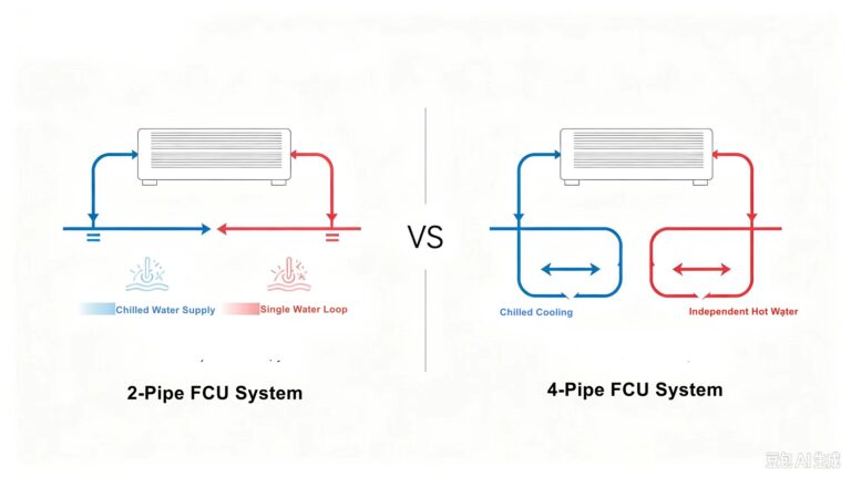
Some thermostats require a jumper or parameter setting to select between 2-pipe and 4-pipe operation. If the setting is incorrect, the thermostat will control the valve using the wrong logic.
Consequence: In a 4-pipe system, the thermostat may only open one valve instead of switching between heating and cooling.
Prevention: Check the thermostat manual for the correct setting before installation. On the T603, the system type is selected in the advanced mode parameters.
Application Pitfalls in Retrofit Projects
1. Assuming All FCU Systems Are Wired the Same Way
In older buildings, FCU systems may have been installed by different contractors using different wiring conventions. A thermostat that worked in one building may not work in another without verifying the wiring first.
Solution: Always perform a site survey before ordering thermostats. Check the existing valve type, fan motor type, and wiring layout.
2. Mixing 2-Pipe and 4-Pipe Components
In a 4-pipe system, the thermostat must control two separate valves — one for heating and one for cooling. If a 2-pipe thermostat is installed in a 4-pipe system (or vice versa), the system will not operate correctly.
Solution: Confirm the system type before installation. On the T603, set the correct System Type in advanced mode parameters.
3. Ignoring the Fan Motor Type
Water-system FCU thermostats are typically designed for 3-speed AC fan motors. If the existing system uses a DC brushless (BLDC) motor or a 0-10V EC motor, the thermostat will not be able to control the fan speed.
Solution: Check the fan motor type before ordering. If the existing motor is not 3-speed AC, a different thermostat or an additional controller may be required.
4. Forgetting the Shared Power Supply
In retrofit projects, the thermostat and the FCU (valve and fan) should share the same power supply. If they are powered from different circuits, ground loop issues can occur, causing communication errors or erratic operation.
Solution: Verify that the thermostat and FCU are on the same circuit. If not, consult an electrician before proceeding.
Why Relay Endurance Testing Matters
One often-overlooked root cause of long-term field issues is relay contact sticking, which can happen after thousands of on-off cycles driving fan and valve loads.
After seeing real-world cases of relay contact sticking in earlier field deployments, our manufacturer now carries out 10,000-cycle 230V AC endurance testing as part of batch-sampling inspection for the T603 series.
This is not 100% unit-by-unit full testing, nor a multi-year warranty — it is one extra practical quality step learned from real-project experience, to lower batch-level failure risk for our wholesale partners.
Pre-Commissioning Checklist
Before powering on the system, use a relay test board or multimeter to verify the following:
- Power supply: L and N connected correctly; voltage within range (100–240V AC)
- Valve wiring: Open/Close terminals connected to the correct valve actuator wires
- Fan wiring: L/M/H terminals connected to the correct fan speed wires
- System type: 2-pipe or 4-pipe setting matches the actual system
- Fan motor type: 3-speed AC motor confirmed; no DC or EC motor connected
- Shared power: Thermostat and FCU on the same circuit
Testing valve and fan outputs before final installation can prevent hours of troubleshooting later.
Understanding the basics of a fan coil unit is essential for successful modern HVAC integration.
Related Reading
- T603 Fan-Coil Thermostat: 2-Pipe vs 4-Pipe System Application Guide
- Budget vs Value-Grade Fan-Coil Thermostats: Total Cost Perspective for HVAC Wholesale ( Coming soon ).
- When to Choose Stand-Alone versus Modbus Thermostats in Building Retrofit Projects ( Coming soon ).
For more technical guides and product information, browse our blog or contact us for wholesale-oriented technical documentation and project support.