
Modbus Thermostat for Office Building Retrofit Projects
In this article, you will learn:
- Why office building HVAC systems need retrofitting
- How to assess an existing FCU system before replacement
- Choosing the Right Thermostat for Retrofit Applications
- Step-by-step wiring and installation for T603 Modbus thermostats
- How to integrate with BMS via Modbus RTU
- Common retrofit challenges and solutions
Click any topic above to jump directly to that section.
Why Office Building HVAC Systems Need Retrofitting
Many office buildings constructed in the 1990s and 2000s still operate on outdated HVAC control systems. An office building retrofit Modbus thermostat upgrade offers a practical, cost-effective way to modernise these systems without replacing the entire HVAC network. The thermostats installed in these buildings are typically standalone units—non-communicating devices that simply turn the fan coil unit (FCU) on or off based on a local temperature reading.
The problem with this approach is straightforward: facility managers have no visibility into room temperatures, no ability to adjust setpoints remotely, and no data to optimize energy usage. When a tenant calls to complain about a cold office, someone has to walk to that room, check the thermostat, and manually adjust it.
For building owners, this translates into higher operational costs, tenant dissatisfaction, and missed opportunities for energy savings. Retrofitting existing FCU systems with Modbus thermostats addresses all three issues without requiring a full HVAC replacement.
This guide focuses on retrofitting existing 2-pipe and 4-pipe fan coil unit systems with T603 Modbus thermostats—a practical, cost-effective upgrade for office buildings.
Assessing the Existing System Before Replacement
Before ordering new thermostats, a site survey of the existing system is essential. Missing a critical detail at this stage can lead to compatibility issues, additional site visits, and project delays.
Check the FCU Configuration
| Question | What to Look For |
|---|---|
| Is the system 2-pipe or 4-pipe? | 2-pipe systems use a single water circuit for both heating and cooling (seasonal changeover). 4-pipe systems have separate heating and cooling circuits, allowing simultaneous heating and cooling in different zones. |
| What is the valve control type? | On/off valves (most common in older systems) or 0-10V modulating valves (less common in retrofit projects). Note that T603 supports on/off valves only. |
| What fan speed control is used? | 3-speed fan control (Low/Medium/High) or 0-10V EC motor control. |
Inspect Existing Wiring
Older buildings often have wiring that does not meet current standards. Check for:
- Wire gauge: Ensure existing wires can handle the load of new thermostats
- Cable condition: Look for insulation cracking, corrosion, or damage
- RS485 wiring: Verify whether shielded twisted-pair cable is already installed—if not, new cabling will be required
Document Existing Thermostat Locations
Note the position of each thermostat. Are they mounted at the correct height (typically 1.4m from the floor)? Are they exposed to direct sunlight, drafts, or heat sources that could affect temperature readings?
Choosing the Right Thermostat for Retrofit Applications
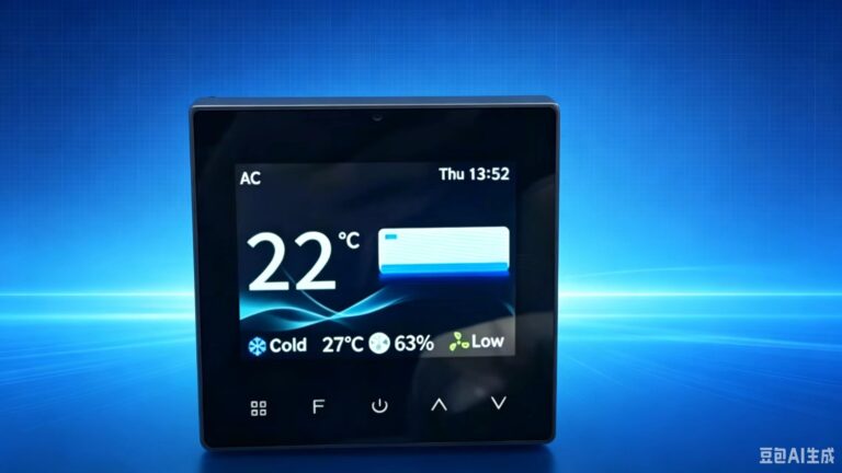
For most office building retrofit Modbus thermostat projects, the T603 provides the functionality needed at a cost point that makes the project viable.
Key Features for Retrofit Projects
| Feature | Benefit for Retrofit |
|---|---|
| RS485 Modbus RTU communication | Integrates with BMS systems via an RS485 port. For Ethernet-based BMS, a Modbus RTU-to-TCP gateway is required. |
| 2-pipe and 4-pipe compatibility | Works with both common FCU configurations found in older office buildings |
| 3-speed fan control | Supports standard fan coil units without requiring motor replacement |
| On/off valve control | Compatible with existing on/off valves—no need to replace valve actuators. Note: T603 supports on/off valves only, not 0-10V modulating valves. |
| Standard 86×86mm mounting | Fits standard wall boxes used in most office buildings, minimizing wall patching |
| TFT display and touch operation | Modern interface that tenants find intuitive and easy to use |
What to Verify with Your Supplier
Before finalizing the order, confirm:
- The specific valve type and voltage in your building (AC/DC, 24V or 230V) to ensure compatibility
- Whether the thermostat supports the existing fan motor type (3-speed AC is standard)
- The communication parameters: default baud rate (typically 9600 bps), parity, and stop bits
Wiring and Installation Steps
Step 1: Power Down and Remove Old Thermostats
- Switch off the power supply to the FCU at the distribution board
- Remove the existing thermostat from the wall, taking care not to damage the wiring
- Label each wire as you disconnect it—this is critical for identifying connections later
- Photograph the existing wiring before removal as a reference
Step 2: Verify and Prepare Wiring
For Modbus RTU retrofits, the RS485 communication wiring requires attention:
- Use shielded twisted-pair cable for the RS485 bus
- Connect A(+) to A(+) and B(-) to B(-) across all devices
- Connect the shield to ground at one end only to avoid ground loops
- For runs longer than 1200 meters or with more than 32 devices, consider a repeater
- A 120Ω termination resistor should be installed at the two far-end devices of the RS485 bus.
Step 3: Mount the New Thermostat
- Install the mounting plate onto the wall box using the supplied screws
- Pull the labeled wires through the base hole
- Connect wires to the appropriate terminals on the T603
Typical terminal connections:
| Terminal | Connection |
|---|---|
| L / N | Power supply (100-240V AC, 50/60Hz) |
| Valve Open / Close | Motorized valve control (on/off) |
| Fan L / M / H | 3-speed fan control |
| RS485 A(+) / B(-) | Modbus RTU communication |
| GND | RS485 ground (optional, if available) |
Note: The thermostat and the FCU valve/fan should share the same power supply to avoid ground loop issues — a common problem in retrofit projects.
Step 4: Configure Communication Parameters
Each T603 thermostat on the same RS485 bus requires a unique Modbus address.
For the exact procedure to set the Modbus address, refer to the T603 product manual or contact our technical support team.
The standard Modbus RTU address range is 1–247. However, the actual number of T603 thermostats that can be connected on one RS485 bus depends on the gateway and bus conditions. Typically, a maximum of 32 devices can be connected without a repeater. For larger systems, an RS485 repeater or multiple buses may be required.
We recommend confirming the maximum number with the gateway supplier before installation.
Step 5: Power On and Test
- Restore power to the FCU
- Check that the thermostat powers on and displays the current room temperature
- Verify fan speed control—each speed should respond correctly
- Test valve operation—listen for the valve actuator opening and closing
- If integrated with BMS, test communication from the central system
Integrating with Building Management Systems
The primary benefit of a Modbus thermostat retrofit is BMS integration.
Typical BMS Integration Setup
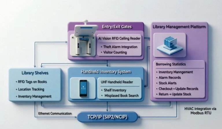
T603 Thermostats → RS485 Bus → Modbus RTU Gateway → BMS
Each thermostat reports:
- Current room temperature
- Setpoint temperature
- Fan speed status
- Valve position (open/closed)
- Operating mode (heating/cooling/auto)
The BMS can send commands to:
- Adjust temperature setpoints
- Change operating modes
- Override fan speeds
- Schedule operation across all zones
Communication Settings
For stable communication across the RS485 bus, ensure all thermostats use identical communication parameters. The T603 default settings are:
| Parameter | Value |
|---|---|
| Baud rate | 9600 bps |
| Data bits | 8 |
| Stop bits | 1 |
| Parity | None |
| Modbus address | 1-247 (unique per device) |
Integration Testing Checklist
- □ Each thermostat responds to a read request from the BMS
- □ Temperature values read match the display on the thermostat
- □ Setpoint changes from the BMS are reflected on the thermostat
- □ Fan speed changes from the BMS are executed correctly
- □ Valve commands are processed without delay
Common Retrofit Challenges and Solutions
| Challenge | Solution |
|---|---|
| Incorrect wiring from previous installation | Use labeled wires and reference photos taken before removal. If labels are missing, use a multimeter to trace each wire back to the FCU. |
| RS485 communication failure | Check A/B polarity, verify termination resistors, and confirm all devices use the same baud rate and parity. Shielding must be grounded at one end only. |
| Valve compatibility issues | Confirm valve voltage and type (on/off vs modulating) before ordering. If the existing valve does not match, it may need replacement. |
| Fan speed mismatch | Verify the existing fan motor is 3-speed AC (most common). DC motors or 0-10V EC motors require different control signals. |
| Address conflicts | Each thermostat on the same RS485 bus must have a unique Modbus address. Document all addresses during installation. |
| Power supply issues | Older buildings may have unstable power. Verify voltage (100-240V AC) and ensure the circuit is not overloaded. |
Related Reading
- What is Modbus RTU and How Does It Work in HVAC Systems?
- RS485 Modbus Thermostat Setup: Step-by-Step Guide
For more technical guides and product information, browse our blog or contact our engineering team for a free consultation.