How to Integrate T603 Smart Thermostats with VRF Systems via AC Gateway
In this article, you will learn:
- T603 VRF Gateway Integration: Why the T603 Needs a Gateway
- How the AC gateway works with the T603
- What the T603 advanced mode parameters mean for gateway setup
- How to configure the T603 for gateway-based control
- Wiring the T603 to the AC Gateway
- Common Gateway Integration Issues
Click any topic above to jump directly to that section.
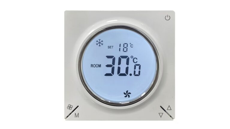
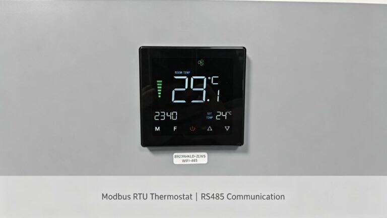
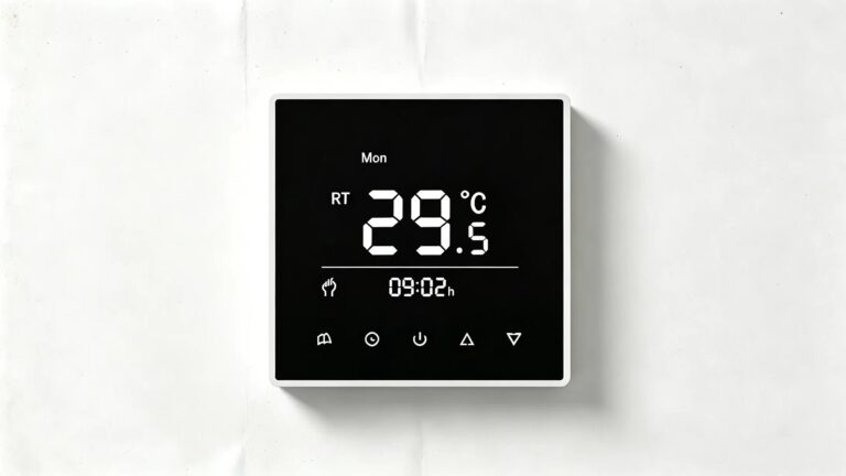
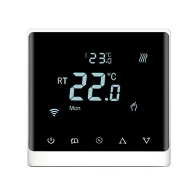
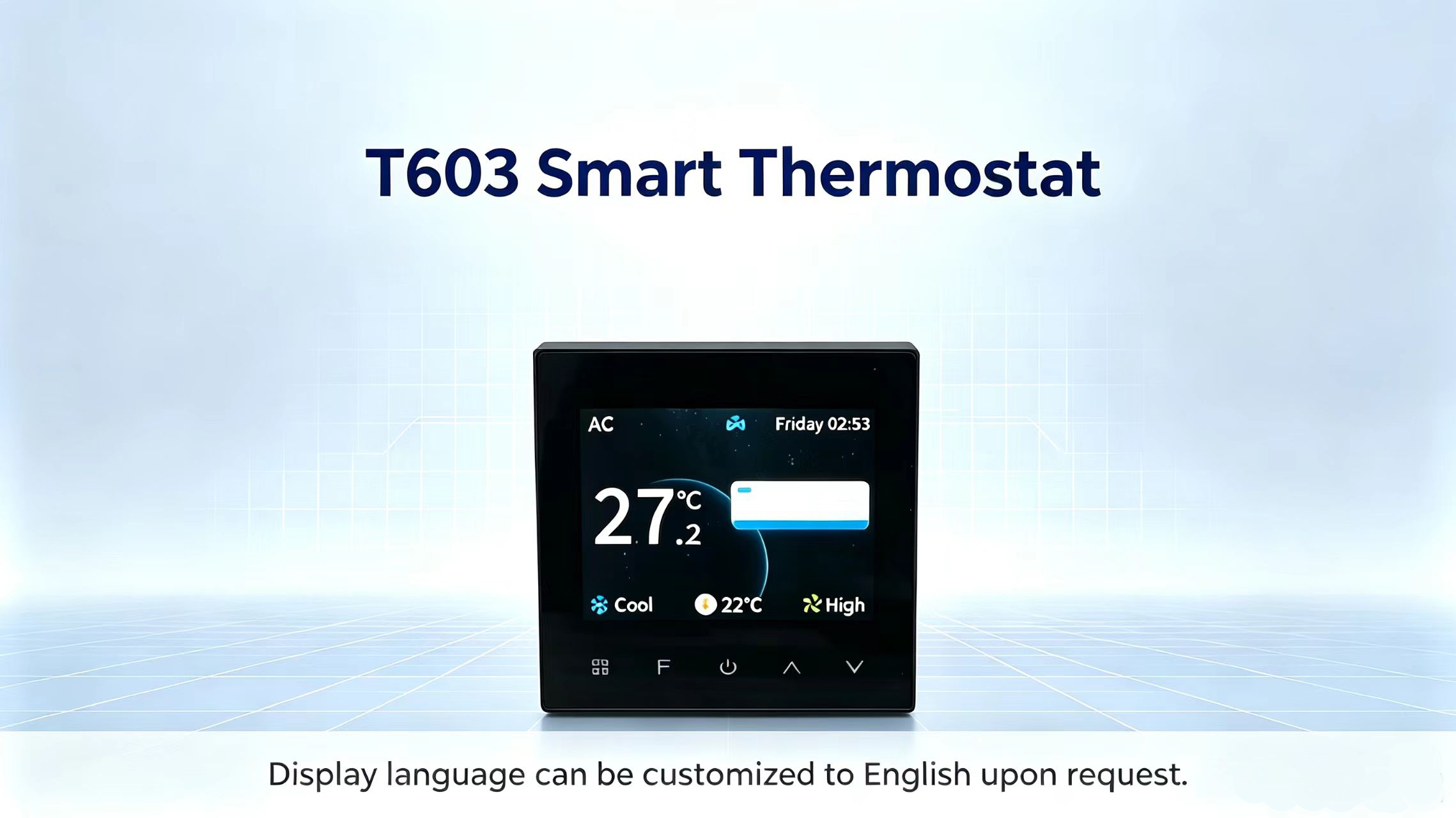
This guide covers T603 VRF gateway integration. The T603 smart thermostat is designed for fan coil units, two-pipe, four-pipe, and VRF/fluorine system air conditioners. But when it comes to controlling VRF systems, there is one important requirement: a dedicated AC gateway is needed.
As stated in the T603 manual: VRF/fluorine system air conditioners must be used with an AC gateway.
This guide explains why the gateway is required, how it works with the T603, and what you need to configure for proper integration.
T603 VRF Gateway Integration: Why the T603 Needs a Gateway
The T603 communicates using Modbus RTU over RS485. VRF (Variable Refrigerant Flow) systems, however, use proprietary communication protocols that are specific to each brand (e.g., Daikin, Mitsubishi, Toshiba, etc.). The T603 cannot directly speak these protocols.
The gateway acts as a translator:
T603 → (Modbus RTU) → Gateway → (VRF protocol) → VRF Indoor Unit
As the T603 manual describes, the T603 controls the VRF system through the gateway, and does not directly activate relay outputs for the air conditioner.
Important: The RS485 port on the T603 is specifically designed for connecting to a VRF gateway. It is not intended for direct connection to a generic BMS. For BMS integration, the gateway provides data to the BMS via its own protocol (e.g., Modbus TCP, BACnet, etc.).
How the AC Gateway Works with the T603
For T603 VRF gateway integration, the T603 communicates with the VRF gateway via Modbus RTU over its dedicated RS485 port. The gateway then translates Modbus commands into VRF protocol commands and sends them to the indoor unit.
Key points from the T603 design:
- The T603 does not control the VRF unit directly — the gateway handles the actual communication
- The T603 sends temperature setpoints, mode commands, and fan speed requests via Modbus
- The gateway translates these into the specific VRF brand protocol
- The gateway also reports back status information (room temperature, fault codes, etc.) to the T603
This means the T603 functions as the user interface and temperature sensor, while the gateway handles the actual system control.
T603 Advanced Mode Parameters for Gateway Setup
The T603 has configurable parameters that affect how it works with the gateway. These are found in the advanced mode settings.
To access advanced mode:
- Turn off the thermostat (power off state)
- Press and hold the Mode button and Fan Speed button simultaneously for 5 seconds
- Use Up/Down buttons to select the parameter
- Press Mode to enter adjustment
- Press Power to save and exit
Key T603 parameters relevant to gateway integration:
| Parameter | Default | Range | Description |
|---|---|---|---|
| System Type | AC + Floor Heating | Two-pipe, AC+Floor Heating, AC+Floor Cooling, Four-pipe, Hydronic Floor Heating, Fresh Air, Refrigerant AC | Select Refrigerant AC for VRF/gateway control |
| Temperature Calibration | -3°C | -10°C ~ +10°C | Adjusts displayed temperature offset |
| Startup Differential | 1°C | 1°C ~ 5°C | Temperature control hysteresis |
| Frost Protection | Off | Off, On | Freeze protection enable/disable |
| Power-On Behavior | Restore previous | Power-on OFF, Power-on ON, Restore previous | Behavior after power failure |
| Minimum Temperature Limit | 05°C | 00°C ~ 34°C | Lower setpoint limit |
| Maximum Temperature Limit | 35°C | 05°C ~ 99°C | Upper setpoint limit |
| Fan Type | AC 3-speed | AC 3-speed, DC 7-speed | Fan motor type selection |
When setting up for VRF/gateway control, ensure System Type is set to Refrigerant AC.
485 Communication Address Setting
The T603 uses Modbus RTU communication over RS485. If multiple T603 thermostats are connected to the same gateway, each thermostat needs a unique Modbus address.
For the exact procedure to set the Modbus address, refer to the T603 product manual or contact our technical support team.
The standard Modbus RTU address range is 1–247. However, the actual number of T603 thermostats that can be connected on one RS485 bus depends on the gateway and bus conditions. Typically, a maximum of 32 devices can be connected without a repeater. For larger systems, an RS485 repeater or multiple buses may be required.
We recommend confirming the maximum number with the gateway supplier before installation.
Wiring the T603 to the AC Gateway
The T603 connects to the gateway via its dedicated RS485 terminals. Do not connect the T603 RS485 port directly to a BMS or other non-VRF devices. Refer to the wiring diagram in the T603 manual for the exact terminal assignments.
The gateway typically requires:
- RS485 A/B connection to the T603
- Power supply for the gateway
- Communication connection to the VRF system (brand-specific)
Important: Always refer to the actual wiring diagram on the T603 bottom case for the correct terminal connections.
Common Gateway Integration Issues
| Issue | Likely Cause | Solution |
|---|---|---|
| No communication with VRF unit | Gateway not powered or wiring incorrect | Check gateway power and RS485 wiring |
| T603 cannot send commands | Incorrect Modbus address or baud rate | Verify Modbus settings match gateway configuration |
| VRF unit does not respond | Gateway protocol setting incorrect | Confirm gateway is configured for the correct VRF brand |
| T603 displays error code | Sensor fault or communication timeout | Check sensor connections and gateway response time |
Related Reading
- What is Modbus RTU and How Does It Work in HVAC Systems?
- Modbus Addressing Explained: A Simple Guide for HVAC Installers
- RS485 Modbus Thermostat Setup: Step-by-Step Guide
For full product specifications, wiring diagrams and further integration guides for VRF projects, visit the T603 product page. You may also browse our blog for more Modbus‑HVAC tutorials or get in touch with our sales team for your free project consultation.